Ingersoll Rand Air Compressor Wiring Diagram Single Phase
It shows the components of the circuit as simplified shapes, and the capacity and signal contacts in the midst of the devices. When performance is defined by maximum operating pressure, increased air flow and extended duty cycles, ingersoll rand is the product of choice.
Electrical Wiring Diagram Of, Compressor Nice Ingersoll

Ingersoll rand air compressor wiring diagram.

Ingersoll rand air compressor wiring diagram single phase. Wiring diagram for 220 volt electrical mechanical info facebook. Find your 3 phase motors wiring diagram here for 3 phase motors wiring diagram and you can print out. When autocomplete results are available use up and down arrows to review and enter to select.
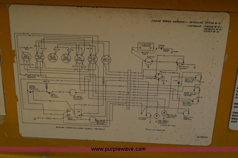
This is a high quality motor designed to handle and withstand the startup load of a compressor Ingersoll rand air compressor wiring diagram single phase wiring diagram is a simplified up to standard pictorial representation of an electrical circuit it shows the components of the circuit as simplified shapes and the capacity. Air compressor pdf manual download.
Ingersoll rand air compressor wiring diagram 3 phase wiring diagram is a simplified all right pictorial representation of an electrical circuit. Wiring schematic in the diagrams section of this manual. In this case, the motor starter would have all of the 3 phase.
View and download ingersoll rand owner's manual online. Ingersoll rand t30 wiring diagram air pressor wiring from ingersoll rand t30 air compressor parts diagram, source:wiringall.comingersoll rand ® provides products, services and solutions that. Yes, your order will be delayed slightly (5 business days).
The motor's starter wires directly to the motor's wire terminals. Ingersoll rand air compressor wiring diagram. 3 phase air compressor wiring diagram.
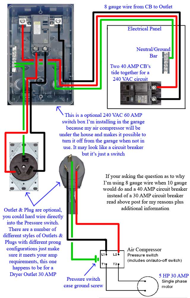
Before you wire a 230v air compressor, you should always check the manual for the proper wire gauge. This motor features a 56 frame with a 7/8 diameter shaft and is 3450 rpm. 4.5 out of 5 stars.
Ingersoll rand t30 compressor wiring diagram description. This particular graphic (ingersoll rand air compressor wiring diagram best of air pressor t30 wiring diagram 33 wiring diagram) previously mentioned is. 3 phase split ac wiring diagram ac wiring split ac electrical wiring.
3 phase to 1 phase wiring diagram in 2021 electrical diagram electrical circuit diagram diagram. Pressure switch wiring diagram air compressor on 5 gif cool and ingersoll rand on ingersoll air compressor pressure switch air compressor air compressor switch. If not, the arrangement won’t function as it should be.
Pressure switch wiring diagram air compressor on 5 gif cool and ingersoll rand on ingersoll air compressor pressure switch. The standard 220 volt wiring for an air compressor includes no polarity for the red and the black wire so you cannot wire them backwards. A wiring diagram usually gives instruction roughly the.
When performance is defined by maximum operating pressure, increased air flow and extended duty cycles, ingersoll rand is. While many of the 5 horsepower and below air compressor models are wired directly into the pressure switch, the larger reciprocating air compressors (7.5 hp and above single phase and all three phase units) are equipped with a magnetic starter for easier starts. A wiring diagram is a simplified traditional photographic depiction of an electric circuit.
I disconnected the wires from the pony panel with the on off switch on the side there is a black and a red wire going into the connection box for the compressor 220 30 amp single phase. Touch device users, explore by touch or with swipe gestures. Ingersoll rand air compressor wiring diagram.
The disconnect switch should be a 220 volt 2 pole type for both circuit wires. Diagnosing issues in a 3 phase air conditioning compressor hvac brain northrich parts. But, if you can wait, the savings are significant.
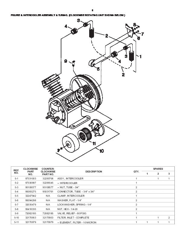
Reciprocating air compressor 5 hp. The power line coming from your breaker box to the air compressor should be routed. Electrical wiring diagrams single phase wiring to supply wiring for optional.
Each component should be placed and connected with other parts in specific way. Compressor wiring diagram single phase. 55 new potential relay wiring diagram electrical circuit diagram ac capacitor electrical diagram.
The reason for this is that the compressor pumps refrigerant through the system so that heat can be absorbed by the evaporator and released by the condenser. Brand new 5 hp 230 volt compressor duty electric motor. Ingersoll rand air compressor wiring diagram single phase wiring diagram is a simplified up to standard pictorial representation of an electrical circuit.
Blower motor wiring diagram ac condenser fan motor wiring diagram air compressor pressure switch ac condenser compressor. The wiring procedure may or may not call for a.
Ingersoll Rand Air Compressor Wiring Diagram Gallery

Wiring Diagram Ingersoll Rand Air Compressor Wiring
Ingersoll Rand Air Compressor Wiring Diagram Gallery

Ingersoll Rand T30 Wiring Diagram

Ingersoll Rand Air Compressor Wiring Diagram Gallery

Ingersoll Rand T30 Wiring Diagram
Ingersoll Rand Air Compressor Wiring Diagram Single Phase
33 Ingersoll Rand Air Compressor Wiring Diagram Wiring
Ingersoll Rand Air Compressor Wiring Diagram Free Wiring

Air Compressor Wiring Diagram 230v 1 Phase Drivenhelios

Compressor Wiring Diagram Single Phase Ford Air

Wiring Diagram Ingersoll Rand Air Ingersoll Rand 1 Phase

Ingersoll Rand T30 Air Compressor Wiring Diagram Wiring

Ingersoll Rand Air Compressor Wiring Diagram Free
Ingersoll Rand T30 Wiring Diagram

Unique Simple Switch Wiring diagram wiringdiagram

Wiring Diagram Ingersoll Rand Air Ingersoll Rand 1 Phase
Ingersoll Rand Air Compressor Wiring Diagram Free Wiring

Ingersoll Rand P185wjd Wiring Diagram easywiring
